Project update
A big thanks to Michael Kubler of Grey Phoenix Productions for his very generous contribution of components, IC's, PIC's and much more which will no doubt come in handy in the build of the project! ![]()
I have also been in touch with several radio amateurs offering both sound advice, and assistance with tracking of the balloon. Thankyou to all who have contacted me and offered input. ![]()
I am currently planning to build a small (50-100g) payload comprising of GPS and a radio transmitter to use for radio testing before the real launch - to get an idea of range & performance.
Another radio test a new yagi
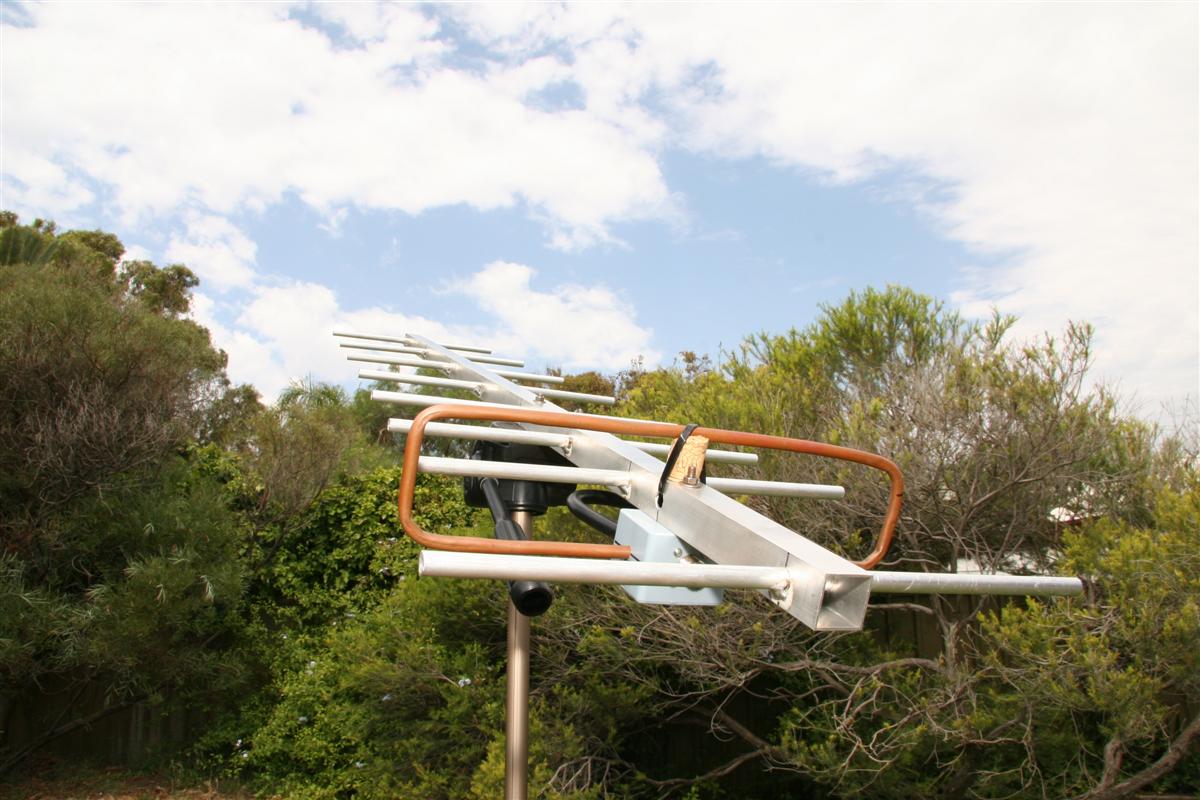
I made up 1.3m yagi yesterday - the biggest that'll fit in the boot of my car ![]() . I used K7MEM's excellent yagi designer to come up with a plan, and cut the pieces from aluminum tubing, which I had TIG welded at a local machine shop for $20. My folded dipole is made from a length of copper tubing, but I don't have much faith in it - it was difficult to get it sized correctly. I suspect I may need to swap it for a better one after I do some proper testing on the antenna.
. I used K7MEM's excellent yagi designer to come up with a plan, and cut the pieces from aluminum tubing, which I had TIG welded at a local machine shop for $20. My folded dipole is made from a length of copper tubing, but I don't have much faith in it - it was difficult to get it sized correctly. I suspect I may need to swap it for a better one after I do some proper testing on the antenna.
We tested the radio again last night, using the coat-hanger yagi, and the larger yagi. The coat-hanger yagi was brilliant considering the effort invested, and is much more practical than the large (1.3m) yagi. It's nowhere near as directional as the larger yagi, given the lower number of elements, and is extremely lightweight - so it's super easy to use with 1 hand.
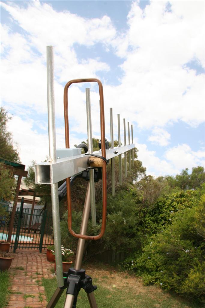
As I found out, two hands are needed for the large yagi, even though it's lightweight (being aluminum). Even using two hands, it's very difficult to keep it exactly on target, and it's extremely directional. I've since made mounted it to the quick release block on my tripod, which should keep it pointing where we want.
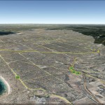
We tested the same distance as previously - from the airport to Belair, as well as going out further with the yagi's. The coat-hanger yagi performed brilliantly at the airport, getting an excellent signal (where the 1/4 wave whip we used last time struggled). Going out further to outer harbor, the coat-hanger yagi was struggling to pickup anything decodeable, but the larger yagi did the trick. Total distance from outer harbor to the transmitter was 27.5km, with a very poor line of sight, and only 300m or so at the transmitter side. Overall quite successful, though I suspect the large yagi is capable of much better performance with some tuning.
-
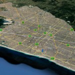
- Windy point -> Outer harbor

-
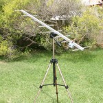
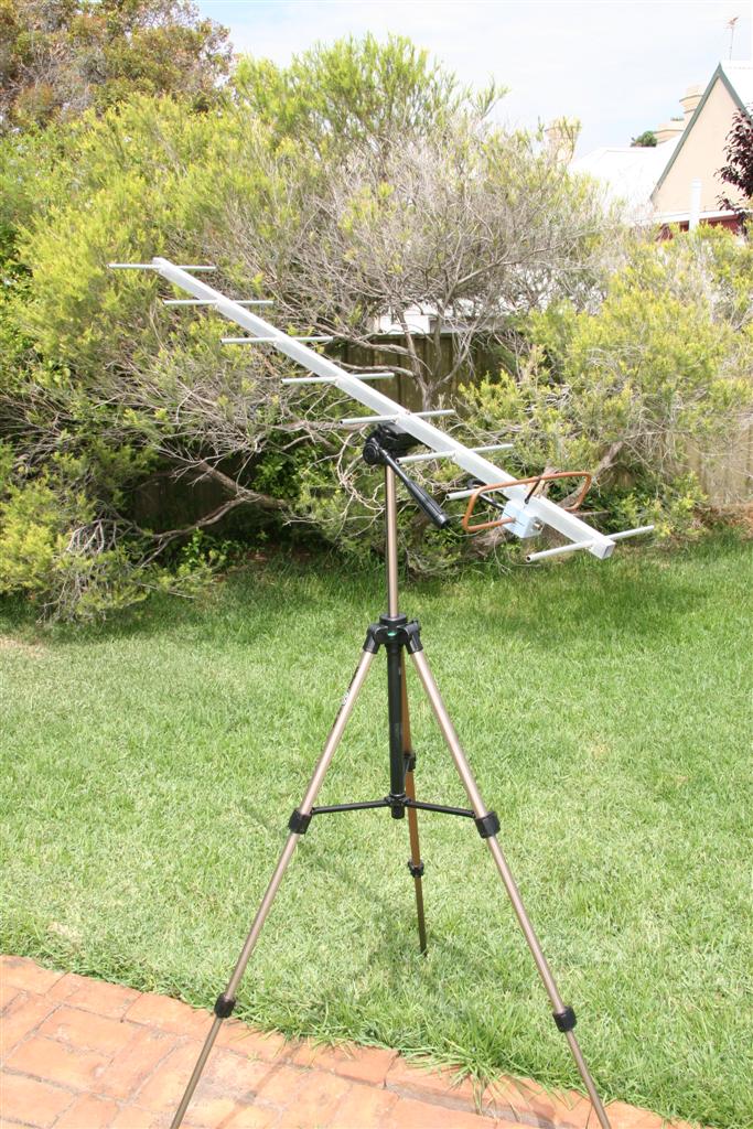
- New yagi mounted on the tripod
-
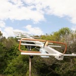
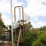
- Horizontally polarized
-
- Vertically polarized
Antennas
I've been busy reading into Yagi antenna design, and have come up with a few designs for the Yagi's we'll use to track the balloon in flight. I'll be building the antennas from aluminium, to keep weight down. I'm planning on a 1.5m long beam, allowing me 10 elements, and a gain of ~14dBi.
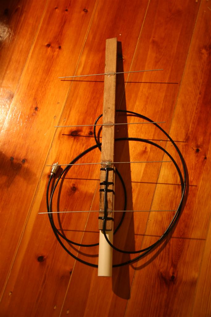
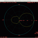
I made up a small 4 element yagi just now, with about $2 of materials - some wood, a few coat hangers, PVC pipe & zip ties. Haven't had a chance to test it properly, but it seems promising. Modeling it in Yagimax suggests a gain of around 9dBi, which is great given the cost & time invested in it. Hopefully will get a chance to make up a long yagi in the next few days as well as test it out.
-
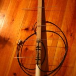
- The 4 element yagi
-
- Modeling the 4 element yagi

Radio testing
I had a chance to test the range of my 25mW Radiometrix NTX2 last night. Whilst we couldn't simulate the true line of sight conditions that we'll see during balloon flight, a few friends and I tested the range of the payload in various conditions. The payload spend the majority of the time on the backseat of my friends car, which would have no doubt limited its range. I used a 1/4 wave piece of exposed coax core as a receiving antenna, sticking it out of the window of my car.
Incidentally, it turns out my car locking/alarm remote is in the same band as the NTX2: ~433mhz, meaning that I wasn't able to unlock/start my car - even after trying my spare keys & scratching my head for a good while.
On flat, straight road with minimal obstruction (a few trees & streetlights), we achieved about 3km of useful (decodeable) range. Given that the antennas were only about 1m above ground level (and probably the street width - it was lined with buildings), we would have had insufficient Fresnel clearance, which would have been a limiting factor.
We decided to position the payload somewhere which might give it better coverage, so headed to Belair, one of the more elevated suburbs in Adelaide. We hoped to test from Windy Point (an elevated lookout with a good unobstructed view of Adelaide), but after arriving and finding a gentleman who was a little too interested in making conversation, we found the prospect of being stabbed a little grisly, so left to find another spot. We settled on a street which was partially shielded by trees & houses, but gave us the best possible line of sight.
One car set off back down the hill to see what sort of range we could achieve - we ended up at the airport (10km away as the crow flies), before I broke the antenna sticking out of my window & we called it a night. Given the pitiful antenna I was using on the receiver & the fact that the NTX2 has the same sort of transmit power as a garage door opener, I was pretty impressed with the range.
I also received another radio I picked up cheaply on eBay today - an ICOM 490A. It's nowhere near as fully featured as my 706, but it'll do SSB on the 70cm band, so it'll decode data just fine.
-
- Radio testing

-
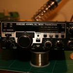
- ICOM 490A
Build update
A fair bit of an update - most of the payload is built, most of the code is written.
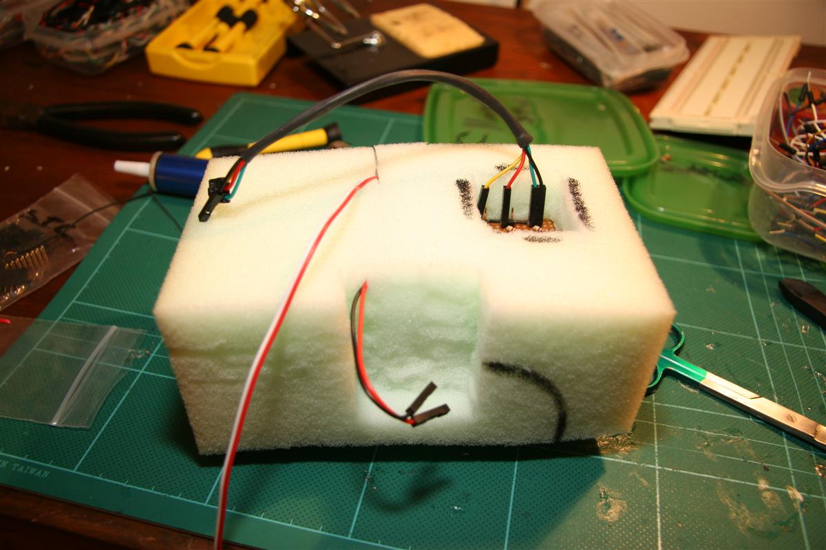
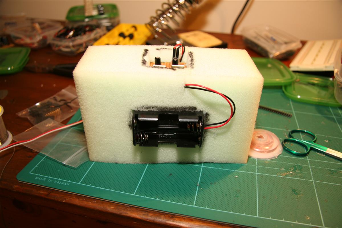
After looking for a suitably sized polystyrene eski/beer cooler for a while & finding almost nothing with the thickness I wanted (25mm+), I gave up and bought a sheet of 50mm polystyrene from a rubber store. I made up a hot wire cutter using some nichrome wire, an old computer power supply and about $10 of wood & steel from my local hardware store, and chopped up what I needed to make a suitably sized box.
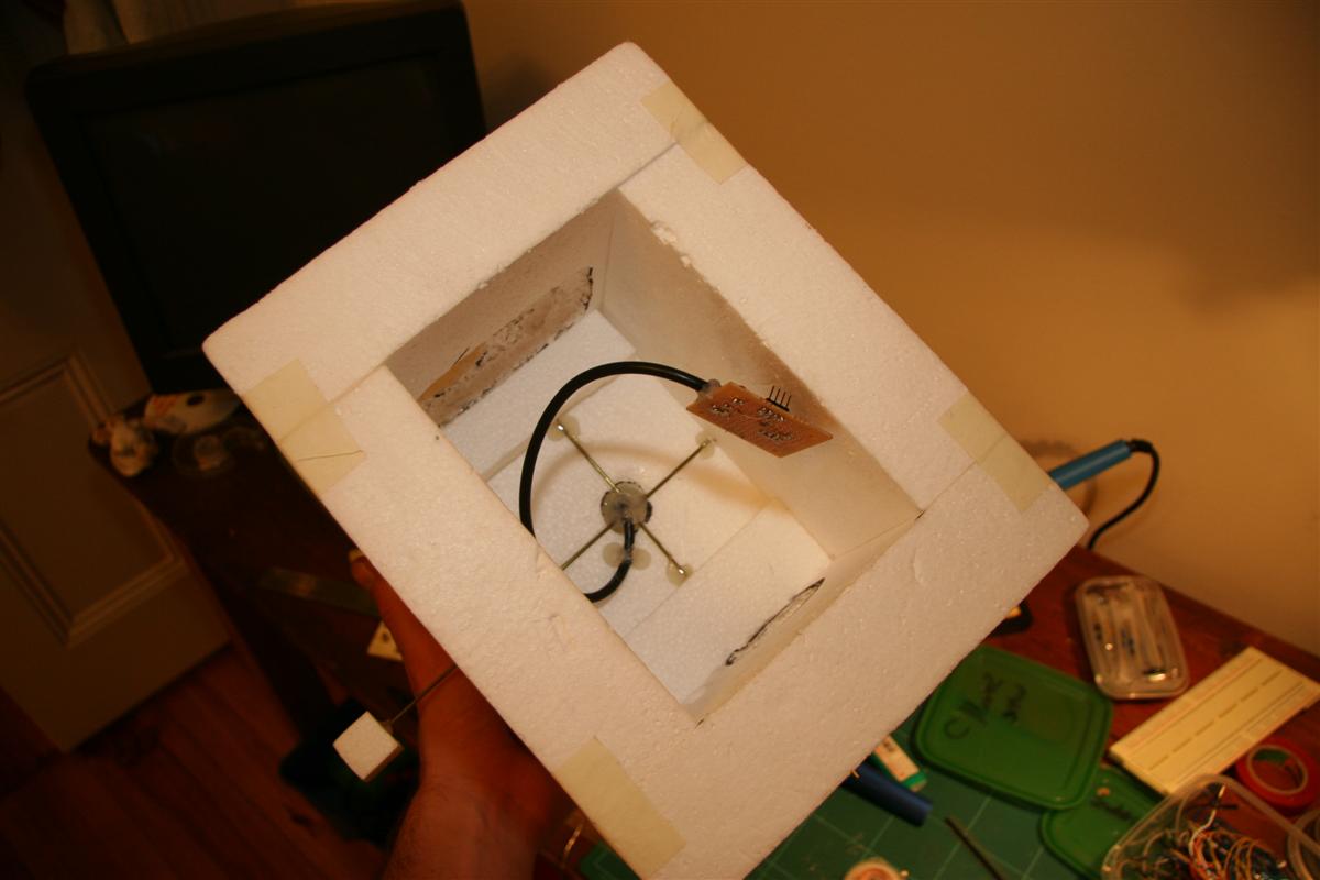
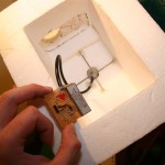
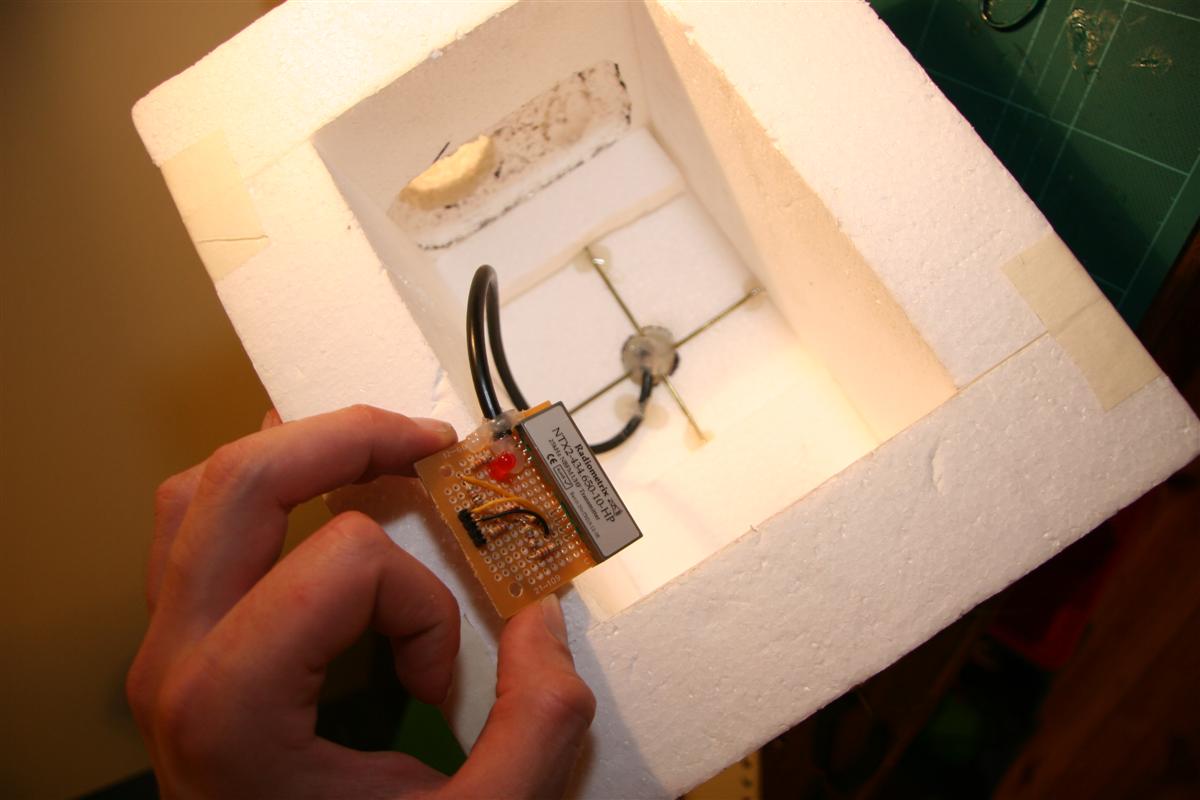
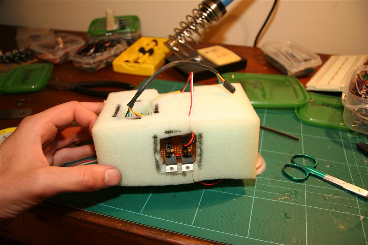
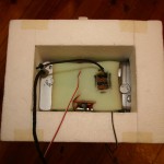
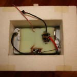
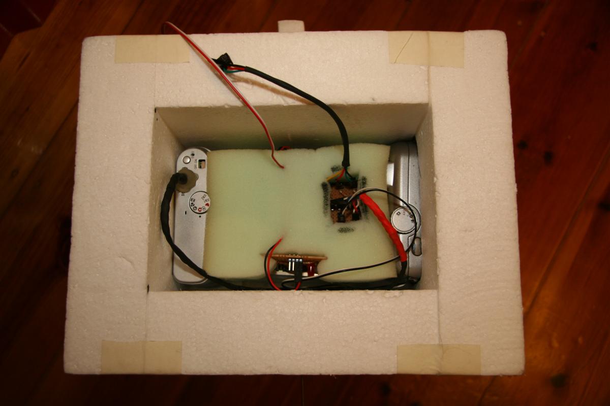
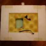
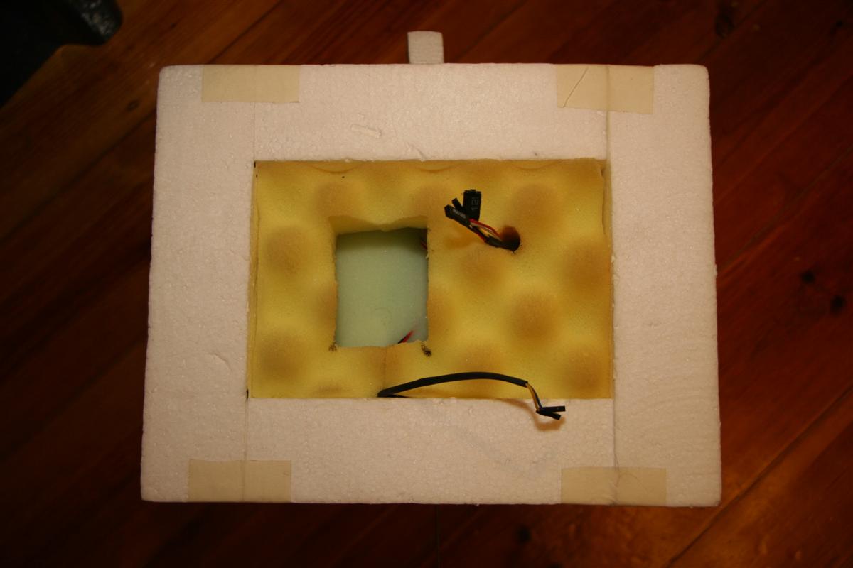
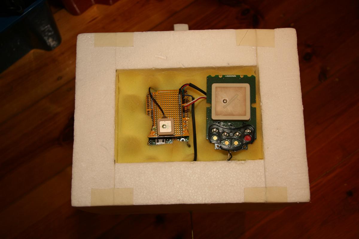
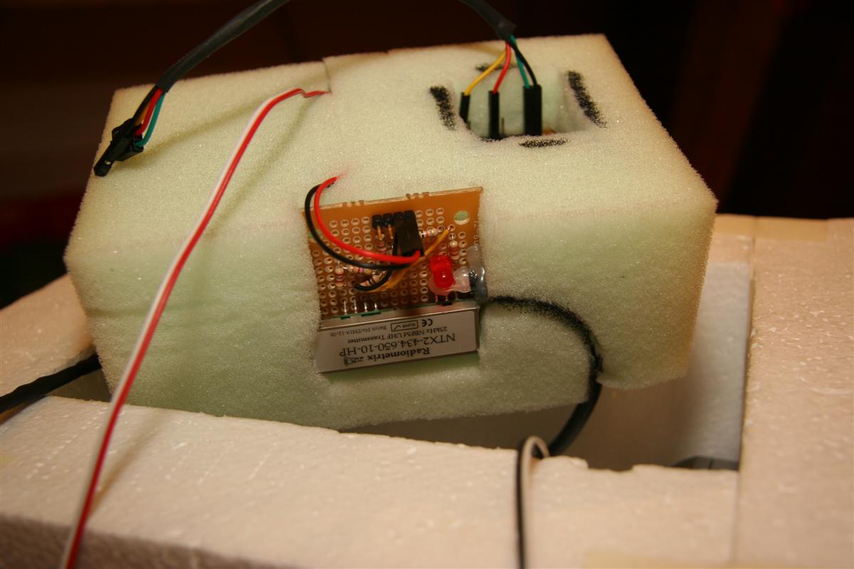
The box is now all cut & joined, with recesses cut for the cameras & antenna installed - the transmit antenna is a 1/4 wave whip with a radial ground plane. Camera lenses are separated from the outside world by UV filters you would use on the end of an SLR lens. I'm quite happy with the way it turned out - the GPS module is up top, next to the (backup) SPOT tracker, both pointing to the sky. Most of the weight is down the bottom, with the cameras & batteries, which should keep things the right way up coming down. All the seperate boards are held in a foam core, keeping everything securely in place.
-
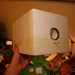
- The payload box

-
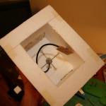
- Inside the payload
-
- Radiometrix + RF out
-
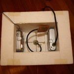
- Cameras inserted
-
- Foam core housing power supply, camera triggers
-
- Power supplies (3.3v 5v)
-
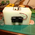
- Battery pack (4x lithium AAs)
- Radiometrix inserted
-
- Foam core in place

-
- Cameras connected to trigger board
-
- Top foam layer inserted
-
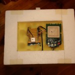
- Flight computer SPOT tracker in place
I've got the flight computer logging its data to an SD card, and have been testing it as a regular GPS logger in the car. The Lassen iQ doesn't seem to be the most sensitive of modules, often losing lock between tall buildings and the like, but this won't be an issue in the open sky. My 12mm coin cell holder arrived, meaning I could solder it down and pop in the GPS backup battery - it now takes about 30 seconds to get a GPS lock when the micro is switched on, as opposed to 5-15 minutes without the backup battery.
I've rewritten sections of the GPS code to be more tolerant of failure & also transmit checkum data on transmitted (radio) strings. Still haven't had another go at flashing the arduino's bootloader, for fear of destroying yet another Atmega. ![]()
Gary from Air Liquide in Elizabeth organised a good price on Helium for us - $100 less than BOC wanted for the same cylinder size. I'm skipping on the idea of using a regulator designed for filling balloons, as the flow rate is too low. Adjustable flow rate oxygen welding regulators are slightly more expensive, but we won't be waiting 3 hours for the balloon to fill.
My balloons and chute will be ordered soon - not long now! ![]()
UKHAS Launches
Just followed the launches of Icarus and Xaben by UKHAS members online. The distributed listener modifications that they've made to fldigi worked amazingly well, the payloads were tracked online flawlessly - much to the credit of jcoxton, rjharrison, fnoble, edmoore & others!
Also got my new Atmega328's, and my Arduino is back from the dead. Haven't yet tried flashing it again.
Exams will be over in a week, soon I can spend some more time building up the payload. ![]()
How to kill an Arduino
I was playing around with the Arduino's watchdog timer the other day - ideally, I'd like to use it to reset the flight computer in case it locks up, or my code goes awry somehow & gets stuck in a loop, etc.
The Atmega328 (the core of my Arduino) does implement a watchdog timer - though unfortunately it's not possible to use it with the standard Arduino bootloader - the reason being that if the watchdog resets the chip, it remains enabled, and worse, its timeout reduces to 15ms - which doesn't give the Arduino bootloader long enough to run any code, so the Arduino gets stuck in a reset loop.
Fortunately, ladyada has written a modification to the Arduino bootloader to work around this problem - all I need to do is reflash the Atmega to use the modified bootloader.
Besides buying a dedicated programmer, the easiest (and cheapest) way to do this is by building a parallel port programmer - an old parallel printer cable, a few resistors and a hacked together ICSP header and I was done - at a cost of $0.
Fast forward to a few minutes later, trying to burn the bootloader into the chip - things are not working well, all I am getting is errors.
Eventually I had another look at my wiring to ensure I hadn't made a mistake (though I did triple check everything) and realised what I'd done. In my rush, I had not read the pin numbers on the parallel cable - I'd based my pinout at looking at the male end of the cable, wheras the diagram I was following was using the female (host) end. So while my leftmost pin was #1, it was #13 in the diagram.
I undid my wiring, and rewired everything up correctly, then tried to reflash to chip - but too late, I'd already toasted it with my first attempts! It no longer runs, and I can't upload any new code to it, so I've ordered a couple of new Atmega328's (they're cheap, thankfully!) which should arrive soon.
I've also been running a few predications with the CUSF flightplan predictor and trying to pick an appropriate launch spot. Whilst I've previously found that winds tend to blow west -> east here, current predications are rather variable, with the possibility east -> west winds (which would land us in the ocean) quite high. It looks like we might need to move further inland for the launch, and keep an eye on the forecasts. I'll also be writing an automatic cutdown system to cut the payload down if it looks like it might drift over populated areas or the ocean.
GPS code
I've uploaded some of the GPS code. Much of it is messy could be re-written, but it works for now.
External triggers code
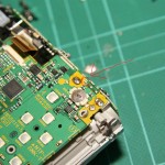
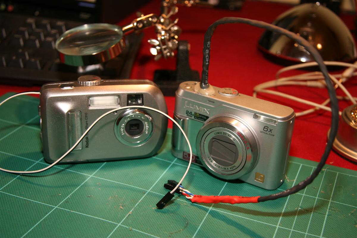
I had a chance to rig up the external trigger on the main camera (the Lumix) this weekend - it didn't go as smoothly as I'd hoped. This camera pretty much kicked my butt - it's usually a good idea to safely discharge the flash capacitor before working inside a camera. Usually you'd do this with a resistor - alternatively, you could forget to do so and accidentally shock yourself half a dozen times. Eventually I de-soldered the capacitor to save myself further pain.
This camera (not surprisingly) was much more intricate and complex than the toy that is the Kodak - it was a bit of work just to reach the shutter button contacts. After eventually getting the right bits off, I decided to test the camera & ensure I was dealing with the right contacts - this went fine, until I touched part of the (metal) casing against the circuit board & smelt smoke.
Much cursing later, I realized I'd blown a fuse - trouble was the size of the fuse - only 1mm or so! I don't have any tiny SMD fuses, much less the skill or tools to solder them, so I bridged the 2 end of the fuse with a drop of solder, which solved the problem.
I eventually got the shutter connected to an external trigger (though this also proved tricky) and put everything back together. There are 4 pins on this trigger - 2 for focus and 2 to release the shutter - though it seems operation on only 2 pins (focus + shutter) is possible.
-
- The wretched fuse
-
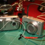
- Both cameras ready to go!
I've also written more code for the GPS side of things - all the useful data is parsed out of the NMEA sentences, checksums are validated, etc.
Also realized my temperature sensors are only good to -40 degrees C, significantly warmer than the payload will be exposed to. I've ordered 2 DS18B20 sensors capable of reaching -55 degrees to replace them.